Payload Kilograms Are Only the Starting Point
Rated payload is useful, but it is only one line in the load case. It does not fully describe where the mass is located, how quickly it must move, or what external forces will act on the system.
When a buyer asks, “Can this head carry 20 kilograms?” the supplier should need more information before giving a responsible answer:
- Where is the combined center of gravity?
- How far is it from the tilt axis?
- What is the payload’s width, height, and projected wind area?
- Are the sensors mounted above, below, or beside the axis?
- Will the system perform slow observation, preset patrols, or rapid target tracking?
- Do external cables create drag or restoring torque?
- Will the platform operate on a fixed tower, vehicle, mast, vessel, or robotic base?
A better procurement document asks for an approved payload envelope rather than one maximum weight figure. That envelope should define mass, dimensions, center-of-gravity limits, mounting pattern, cable routing, and the permitted motion profile.
Calculate Static Moment Before Reviewing Motor Torque
The first engineering check is the static moment about the tilt axis. In simplified form:
M = m × g × e
Where:
- M is the static moment at the tilt axis
- m is the payload mass
- g is gravitational acceleration
- e is the perpendicular offset between the payload center of gravity and the tilt axis
The important variable is often not mass but offset. Moving the center of gravity farther from the axis increases the required holding torque in direct proportion. A long optical assembly can therefore be more demanding than a heavier but well-balanced enclosure.
This is why a sensor list is not enough. The supplier needs an assembly drawing showing:
- Mass of each sensor and bracket
- Center-of-gravity location for each component
- Combined center of gravity after assembly
- Distance from the combined center of gravity to the tilt axis
- Movement of the center of gravity when a zoom lens, focus group, wiper, or external accessory changes position
Where possible, design the payload so its center of gravity remains close to the tilt axis. Balancing the assembly reduces holding torque, motor current, heat generation, gearbox loading, and stress on the mounting structure.
Rotational Inertia Determines How Difficult the Payload Is to Move
Static moment describes the force needed to hold an unbalanced payload. Rotational inertia describes how strongly the payload resists changes in angular speed.
A simplified representation is:
J = Σ(m × r²)
Where J is rotational inertia, m is the mass of each component, and r is its distance from the rotation axis.
The squared distance is significant. A sensor or illuminator mounted twice as far from the axis contributes approximately four times as much to rotational inertia, assuming the same mass and a simplified point-mass model.
This directly affects acceleration, stopping distance, directional reversal, and control-loop tuning. Approximate dynamic torque can be considered as:
Tdynamic ≈ J × α + Tfriction + Tcable + Twind
Where α is angular acceleration and the remaining terms represent drivetrain friction, cable resistance, and external wind torque.
For a multi-sensor payload, request an inertia estimate or provide enough mechanical data for the pan-tilt supplier to calculate it. Payload mass alone cannot predict tracking performance.
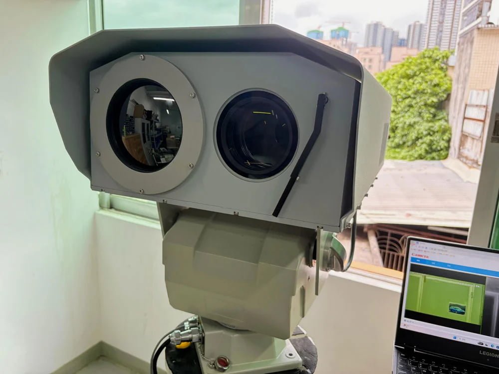
A heavy-duty pan-tilt platform should be selected using payload mass, center of gravity, inertia, and motion requirements.
Build a Payload Mass and Center-of-Gravity Table
Before selecting a platform, create one table covering every item that moves with the head. Do not count only the main cameras.
- Visible zoom camera and lens
- Thermal imaging module and thermal lens
- Laser rangefinder
- Laser or infrared illuminator
- GPS, compass, inclinometer, or weather sensor
- Edge processor or encoder
- Internal power and communication modules
- Protective windows, sunshields, wipers, and housings
- Mounting plates, side brackets, fasteners, and counterweights
- Moving cable harnesses and connectors
For each item, record mass and X, Y, and Z center-of-gravity coordinates relative to a common datum. Calculate the combined center of gravity for the complete assembly, not only the optical payload.
This table also makes future customization easier. If an OEM buyer changes the thermal lens or adds a rangefinder, the engineering team can see whether the new configuration remains inside the approved envelope.
Separate Observation Platforms From Tracking Platforms
Long-range observation
Long-range observation generally prioritizes low-speed smoothness, stable holding, controlled preset movement, and minimal image disturbance at narrow fields of view. Maximum speed may be less important than the ability to make very small movements without stick-slip, overshoot, or visible oscillation.
Target tracking
Tracking applications place more emphasis on acceleration, reversal, control latency, velocity consistency, and the ability to follow target coordinates from radar, analytics, or another sensor.
Patrol and alarm verification
Perimeter and critical-infrastructure projects may require a mixed profile: slow patrol, rapid movement to an alarm preset, stable dwell for verification, and then a controlled return to patrol.
The RFQ should provide the required motion profile rather than one maximum speed value:
- Minimum controllable speed
- Normal patrol speed
- Maximum repositioning speed
- Required acceleration and deceleration behavior
- Typical travel angle between presets
- Expected number of movements per hour
- Continuous-duty or intermittent-duty operation
- Required settling time after movement
A pan-tilt positioner that looks fast in an unloaded demonstration may behave differently after a large optical payload and external cable set are installed. Sample testing should use the intended mass, center of gravity, and motion profile.
Evaluate the Drive Architecture as a Complete System
Motor type is only one part of the motion system. Buyers should review the motor, transmission, encoder, bearings, controller, brake or self-locking behavior, structural frame, and software tuning together.
Gear-driven systems
Gear-driven architectures can provide torque multiplication and compact packaging. The engineering review should examine backlash, stiffness, wear, lubrication, output-bearing support, and the effect of directional reversal.
Worm-drive systems
Worm-drive arrangements may be considered where high reduction, load holding, and robust low-speed operation are priorities. Buyers should still ask about efficiency, thermal behavior, backlash management, serviceability, and performance during frequent reversal.
Direct-drive systems
Direct-drive architectures can reduce mechanical transmission elements and may support responsive motion. Their suitability depends on required torque, bearing arrangement, encoder feedback, controller tuning, thermal design, and cost.
No architecture is automatically best for every project. A slow, heavy observation platform and a fast anti-drone tracking platform impose different requirements.
Ask Where the Position Encoder Measures
Encoder resolution is often promoted as a precision specification, but encoder placement matters.
An encoder on the motor shaft measures motor rotation. If gears, belts, couplings, or flexible elements sit between the motor and output axis, their backlash and compliance may not be fully represented by motor-side feedback.
An encoder measuring the output axis can provide more direct information about the actual pan or tilt position. Some designs may use both motor feedback and output-axis feedback.
Ask the supplier:
- Is position feedback measured at the motor or output axis?
- Is the position reference incremental or absolute?
- What happens to position information after power loss?
- How is gearbox backlash handled during direction reversal?
- Is repeatability measured from one approach direction or both?
- Does the stated accuracy include the payload, bracket, and external cable?
- What settling time is used before the position is measured?
These questions are more useful than comparing encoder bit counts without understanding the full mechanical chain.
Optical Stability Becomes More Demanding at Narrow Fields of View
At long focal lengths, a small angular error can create a large apparent movement in the image. The problem may come from gearbox backlash, structural flex, bearing clearance, mounting vibration, wind, cable force, or control-loop oscillation.
For visible, thermal, and laser payloads, evaluate:
- Line-of-sight stability while stationary
- Image motion during low-speed pan and tilt
- Overshoot after a preset movement
- Settling time before the operator can verify a target
- Drift during extended dwell
- Repeatability when approaching a preset from opposite directions
- Vibration introduced by wipers, fans, rotating equipment, or the mounting structure
For thermal-visible-rangefinder assemblies, boresight alignment also matters. The supplier and integrator should define how the optical axes are aligned, how alignment is checked after transportation, and whether the system requires field adjustment.
Specify Environmental Exposure Precisely
“Outdoor use” is not a complete environmental specification. Coastal salt, desert dust, industrial pollution, freezing rain, high solar load, and vehicle vibration create different design problems.
The RFQ should identify:
- Operating and storage temperature requirements
- Rain, dust, humidity, condensation, and icing exposure
- Salt atmosphere or corrosive industrial environment
- Solar radiation and enclosure heat load
- Fixed-site, vehicle, mast, tower, or marine installation
- Expected vibration and mechanical shock
- Lightning, surge, grounding, and electrical protection requirements
- Required maintenance interval and site accessibility
The IEC explains that IP ratings classify enclosure protection against dust and liquid intrusion. An IP code does not, by itself, describe corrosion resistance, vibration, temperature capability, optical-window performance, or long-term seal ageing. Review those requirements separately.
External reference: IEC Ingress Protection ratings.
Cable Management Is Part of the Mechanical Load
Cables can disturb motion, increase torque, limit travel, and damage connectors. A platform may move correctly during an open-bench test but behave differently after the complete cable harness is installed.
Review:
- Power, network, serial, video, synchronization, heater, wiper, and sensor cables
- Cable bend radius
- Cold-temperature cable flexibility
- Connector retention and strain relief
- Internal or external cable routing
- Required continuous-pan capability
- Slip-ring channel count, current, bandwidth, and signal type where applicable
- Separation of power and sensitive signal paths
- Service loops and maintenance access
Include cable drag in motion testing. An external harness that pulls harder at one end of travel can change low-speed performance and preset repeatability.
Define Control and Feedback Before Hardware Approval
PTZ motion control requirements should be written as system behavior, not only as a list of protocol names.
Clarify whether the platform must support:
- Absolute-position commands
- Relative-position commands
- Velocity control
- Preset storage and recall
- Patrol routes
- Position, speed, alarm, and fault feedback
- Radar or analytics coordinate input
- Time synchronization
- Remote diagnostics and firmware update
- Integration with a VMS, command platform, or OEM controller
The exact electrical interfaces, network functions, command set, protocol documents, and supported integration methods must be confirmed for the selected JEC configuration.
Design the Mounting Interface Around Real Loads
The pan-tilt head is only as stable as the structure beneath it. A rigid head installed on a flexible pole can still produce unstable long-range video.
Ask the mechanical team to review:
- Base bolt pattern and fastener grade
- Mounting-surface flatness
- Pole or tower torsional stiffness
- Natural frequency of the support structure
- Foundation and anchor design
- Access for cable installation and service
- Drainage and water traps
- Galvanic compatibility between dissimilar materials
For mobile platforms, include vehicle motion, mast flexibility, braking loads, road shock, vessel roll, or robotic-base acceleration in the load case.
Use a Payload Mock-Up During Factory Acceptance Testing
Do not approve the system using an unloaded head or a compact test weight fixed directly over the axis. A useful factory acceptance test should reproduce the intended mass, center-of-gravity offset, projected area, cabling, and motion profile.
Recommended mechanical tests
- Full-range pan and tilt movement with representative payload
- Low-speed smoothness in both directions
- Acceleration, stopping, and rapid reversal
- Preset repeatability from clockwise and counter-clockwise approaches
- Holding drift during extended dwell
- Cable behavior across the full travel range
- Power interruption and position recovery behavior
- Inspection for unexpected noise, heat, looseness, or vibration
Recommended optical tests
- Visible image stability at the longest intended focal-length range
- Thermal image stability during motion and dwell
- Thermal-visible boresight alignment
- Rangefinder or illuminator alignment where included
- Settling time after preset movement
- Target reacquisition after repeated patrol cycles
Prepare an Engineering RFQ, Not a One-Line Price Request
NIST’s video surveillance equipment selection guide begins with the definition of user requirements before equipment selection. The same principle applies to motion platforms: define the surveillance assignment and functional requirement before comparing specifications.
External reference: NIST Video Surveillance Equipment Selection and Application Guide.
A useful RFQ for payload integration should include the following information.
Payload package
- Component list and individual masses
- Complete assembly mass
- Combined center-of-gravity coordinates
- Estimated pan and tilt inertia
- Overall dimensions and projected area
- Mounting drawing and 3D model where available
Motion profile
- Minimum and maximum speed expectations
- Acceleration and reversal requirements
- Preset use and patrol sequence
- Tracking or radar-cueing requirement
- Duty cycle and expected movements per hour
- Required settling time and pointing stability
Installation environment
- Fixed, vehicle, tower, mast, robotic, or marine installation
- Temperature, rain, dust, humidity, corrosion, and wind conditions
- Support-structure drawing
- Power, grounding, and surge-protection plan
- Maintenance access and required service interval
Control and documentation
- Required command interface and system architecture
- Position and fault-feedback requirements
- VMS, radar, analytics, or OEM-controller integration
- Mechanical drawing, interface document, wiring diagram, and protocol document
- Factory acceptance and site acceptance criteria
- Sample, pilot, and batch-order timeline
Procurement Warning Signs
Pause the evaluation when a proposal provides:
- A payload rating without a center-of-gravity limit
- Maximum speed without stating the test payload
- Position accuracy without a test method
- Encoder resolution presented as complete system accuracy
- No output-axis or mounting-interface drawing
- No cable-routing plan for continuous pan
- No distinction between operational and survival wind
- No loaded sample test before project approval
- No explanation of spare parts, field service, or model lifecycle
These gaps do not automatically mean the product is unsuitable. They mean the engineering evaluation is incomplete.
Where JEC Fits
JEC maintains a dedicated heavy-duty pan-tilt head product page for long-range and critical-infrastructure projects. Buyers can also review JEC’s long range surveillance camera systems, multi-sensor thermal PTZ platform, and the technical article about servo and stepper PTZ motor control.
For an industrial PTZ camera project, send JEC the complete payload mass, center-of-gravity drawing, dimensions, motion profile, installation environment, cable list, control architecture, quantity, and schedule. JEC can use that information to discuss a suitable project-based platform and acceptance-test plan.
Rated payload, center-of-gravity limits, speed, acceleration, positioning performance, environmental ratings, interfaces, protocols, drawings, lead time, and customization scope must be confirmed for the selected configuration before publication or purchase.
Request a Payload Engineering Review
Send JEC your payload drawing, component weights, combined center of gravity, dimensions, expected wind area, motion profile, installation environment, control requirements, quantity, and project schedule. This information allows the engineering discussion to begin with real load conditions rather than a single payload kilogram figure.
Contact JEC to discuss a heavy-duty pan-tilt platform for your multi-sensor project.