Approve pan-tilt integration against three defined paths: motion control, payload data and payload power. Specify their connections and acceptance conditions, then test them together on the assembled payload. Continuous rotation alone does not establish the performance of the installed electrical interfaces.
For one UGV integration project, the customer selected the JEC-PTU-720 platform, with its ability to carry the required payload confirmed for that configuration. This project-specific confirmation does not change the published 1.7 kg rating.

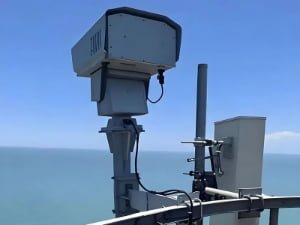
JEC-PTU-720 standalone pan-tilt platform.
Define the Control, Data and Power Interfaces
The interface specification should distinguish the stationary base from the rotating payload and assign responsibility for every connection.
| Path | Connection | Required definition |
|---|---|---|
| Motion control | Command host to PTU controller | Host location, physical interface, protocol, feedback and stop behaviour |
| Payload data | Cameras and sensors to base network | Rotating interface, Ethernet format, traffic requirement and connector assignments |
| Payload power | Supply to moving devices | Delivered voltage, branch and shared limits, peak loads and protection |
Define whether the purchase covers a bare PTU, empty sensor cabins or a complete camera system. Allocate the sensors, harness, switch, converters and assembly work explicitly.
Ethernet passthrough and Ethernet motion control are different functions. Pelco-D specifies commands, while RS485 or RS422 identifies a physical interface. The control specification should identify the actual command endpoint and any required adapter.
A payload-side switch still requires a documented connection across the rotating boundary. Include both traffic directions where the payload computer must receive commands and transmit sensor data.
Validate Ethernet During Rotation
For pan-tilt Ethernet passthrough, measure the installed path using the intended camera streams and sensor traffic. Negotiated link speed is not equivalent to usable application throughput.
Moog’s Ethernet and slip-ring technical paper explains the signal-quality considerations of rotating interfaces. It does not establish the bandwidth of a particular JEC configuration.
Establish a stationary baseline, then repeat the test during the specified movements and simultaneous payload operation. Retain:
- Throughput, packet-error and link-loss records.
- Video interruptions, device restarts and reconnection behaviour.
- Motion direction, speed, duration and configuration revision.
Agree acceptance limits before testing. Associate each result with the installed harness and operating conditions so later configuration changes can be assessed.

Document Payload Power at the Load
The PTU input supply does not necessarily equal the voltage delivered to the payload. Trace each load through the approved power diagram, including conversion stages, returns and protection.
For each device, record its operating voltage, steady demand, startup current and supply branch. Identify which devices operate simultaneously and whether the motor/controller shares the upstream supply budget.
Two side-mounted cabins do not establish independent power allowances. Distinguish per-branch limits from the shared total and assess conversion losses separately. Measure voltage at the payload connectors under the agreed load; a reading at the base supply is insufficient.
Any change to regulators, protection or wiring requires an approved electrical design.
Specify UGV Stability Separately
Holding an encoder angle relative to the vehicle differs from maintaining an external line of sight while the vehicle tilts. Define the compensation axes, reference frame, base-motion conditions and permissible image movement.
Position recovery does not establish inertial stabilization. Include stabilization in acceptance testing only when it forms part of the ordered configuration. Vehicle shock and environmental exposure require separate assessment.
Control the Integration Documents
The integration package should contain:
- External dimensions, mounting datums, connector access and motion clearances.
- Interface and wiring drawings with connector views and pin numbering.
- Power allocation, protection and integration responsibilities.
- Ordered options, harness revision and relevant firmware versions.
- Acceptance conditions and designated reviewers.
A dimensioned drawing or simplified external model can support fit checks without disclosing internal manufacturing CAD. Evaluate mechanical loading through the separate payload mass and center-of-gravity checks.
Review changes to cameras, switches, lighting or cables against the approved configuration, even when the external dimensions remain unchanged.
Define Sample Acceptance Before Ordering
An Acceptance Test Procedure (ATP) should link each requirement to a measurement and retained record.
| Check | Acceptance evidence |
|---|---|
| Assembly and electrical compatibility | Matching BOM and harness revisions; reviewed pinout, supply rails and protection before energizing |
| Control from the intended host | Movement, stop and required feedback records |
| Data during rotation | Traffic results, link events and video observations under specified motion |
| Simultaneous power demand | Payload voltage and current measurements at defined points |
| Recovery and contracted stabilization | Results against separately agreed fault-recovery and motion conditions |
Use the intended payload where possible. Document substitutions and assign owners and closure dates to outstanding tests. Follow the installed-system commissioning checklist for subsequent installation checks.
Frequently Asked Questions
Is Ethernet passthrough the same as PTU control?
No. Passthrough transfers payload data; PTU control addresses the motion controller. Specify both connections independently.
Does continuous pan establish continuous data and power operation?
No. Validate the installed data and power paths during the required motion profile.
Can the PTU input voltage be used as the payload voltage?
Only if the approved electrical design provides that rail. Check the delivered voltage at each load.
How should two payload cabins be budgeted?
Calculate each branch and the simultaneous total, including startup demand and conversion losses. Apply the documented shared limits.
Which documents are needed before sample testing?
External fit drawings, versioned interface and wiring documents, a power budget and an agreed acceptance procedure.
Request a Payload Interface Review
For other assemblies, compare JEC pan-tilt platforms against the actual payload and operating task. Provide the payload list, mass, center of gravity, target type and distance task, installation environment, supply requirements, control platform, Ethernet topology and sample or batch quantities.
Request a Payload Interface Review with the relevant drawings and proposed acceptance conditions.
The approved sample configuration should become the reference for batch orders. Record deviations in the order conditions, including responsibility and closure dates. Procurement can then distinguish an accepted design from an outstanding engineering requirement.