Most perimeter-camera specifications begin with hardware: thermal resolution, visible zoom, pan speed and enclosure rating. That order is convenient for comparing datasheets, but it is not how an industrial perimeter actually operates.
When an alarm occurs at a substation, logistics yard, manufacturing plant or energy facility, the operator does not need two technically impressive video channels. The operator needs a sequence that works: locate the activity, place the correct sector on screen, understand what caused the alarm and decide whether a response is necessary.
A dual-sensor thermal PTZ camera is useful only when its thermal channel, visible channel and motion platform support that sequence as one system. Poorly matched optics, unstable positioning or an incomplete VMS workflow can reduce the value of otherwise capable sensors.
This selection guide examines the engineering and procurement questions that matter to security integrators, distributors, OEM/ODM buyers and project contractors designing professional perimeter surveillance systems.
Begin With the Perimeter Architecture
Before selecting a camera, divide the site into operational zones. A perimeter may include a straight fence line, vehicle gate, service road, loading yard, storage area, transformer yard and several blind approaches. These zones rarely have the same observation distance, background temperature, lighting or response priority.
A useful site plan should identify:
- Protected boundaries and restricted areas
- Likely pedestrian and vehicle approach routes
- Existing gates, lighting, fixed cameras and access-control points
- Areas covered by fence sensors, radar or video analytics
- Minimum and maximum observation distances for each sector
- Hot equipment, steam outlets, reflective surfaces and moving machinery
- Camera mounting positions, mounting heights and possible obstructions
- Areas that must remain under continuous observation
This exercise determines what the PTZ is expected to do. In one project, it may investigate alarms generated by fixed thermal cameras. In another, it may patrol several low-risk sectors and move to a preset when a fence sensor activates. A mobile patrol unit may use the PTZ for active inspection rather than continuous perimeter coverage.
These are different operating models. They should not be placed under one generic requirement such as “360-degree thermal surveillance.”
A PTZ Is an Investigator, Not a Permanent View of Every Sector
A PTZ can observe many directions, but it can look closely at only one direction at a time. This limitation is often overlooked in early project drawings.
Suppose one PTZ is responsible for four separate fence sectors. While it is zoomed into Sector A, it is not simultaneously providing a detailed view of Sectors B, C and D. Preset patrols improve coverage over time, but they do not create continuous observation of every sector.
For higher-risk sites, a more resilient architecture often separates detection from investigation:
- Fixed thermal cameras, radar or fence sensors maintain continuous awareness in assigned zones.
- The PTZ moves to the alarm location for closer inspection.
- The thermal channel helps locate the relevant heat signature.
- The visible channel provides additional scene context when conditions permit.
- The VMS records the event and presents the relevant information to the operator.
This does not mean every perimeter requires fixed thermal cameras. It means the system designer must state whether the PTZ is the primary detection device, an alarm-verification device or both.
Give the Thermal and Visible Channels Separate Jobs
The two channels of a thermal PTZ camera should not be treated as interchangeable versions of the same image.
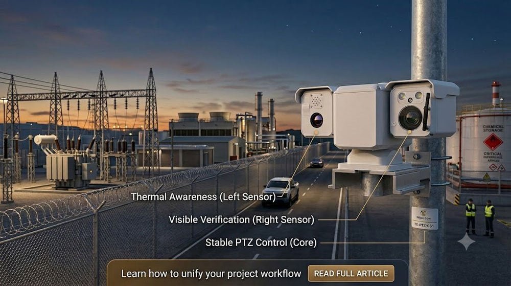
The thermal channel
Thermal imaging represents differences in emitted infrared energy. It does not require visible illumination in the same way as a conventional camera, which can make it valuable around dark fence lines, uneven lighting, backlit areas and sites where switching lights or headlights make visible observation inconsistent.
Its project role may include:
- Locating a person or vehicle against a complex background
- Checking a dark approach road before visible confirmation
- Supporting analytics in a defined thermal scene
- Following a heat signature while the operator adjusts the visible channel
- Providing useful observation when visible contrast is poor
The visible channel
The visible camera provides information that thermal imagery may not show clearly, including scene color, clothing color, vehicle markings, equipment condition and contextual detail.
Its role may include:
- Confirming whether movement is associated with a worker, intruder, animal or vehicle
- Checking whether a person is inside or outside a controlled boundary
- Examining gates, doors, identification markings or carried objects
- Recording conventional video for incident review
- Providing a more familiar image for control-room operators and response teams
A well-designed EO/IR PTZ camera workflow does not simply offer a button for changing channels. It defines when each channel is used, what the operator expects to learn from it and how the target remains in view during the transition.
Lens Matching Is a Geometry Problem
One of the most common procurement errors is comparing the thermal focal length directly with the visible focal length. A 25 mm thermal lens and a 25 mm visible lens do not necessarily produce the same view because the two sensors may have different physical dimensions and pixel formats.
For each channel, the approximate horizontal field of view can be calculated as:
Horizontal field of view = 2 × arctan(sensor width ÷ 2 × focal length)
Once the field of view is known, the approximate scene width at a selected distance can be estimated:
Scene width = 2 × distance × tan(horizontal field of view ÷ 2)
The estimated number of horizontal pixels covering a target can then be considered:
Target pixels = target width ÷ scene width × horizontal image pixels
These calculations are more useful than quoting focal length alone. They allow the integrator to compare what each channel will show at the actual project distances.
For example, the design team should check whether:
- A target detected near the edge of the thermal frame will also appear inside the visible frame.
- The visible camera opens at an appropriate zoom position after an alarm.
- The visible channel provides enough scene context before the operator zooms further.
- The thermal view is wide enough for the assigned alarm zone.
- The selected lenses remain useful at both the closest and farthest points in the sector.
The procurement requirement should describe the intended result rather than prescribe unrelated lens numbers. A practical statement might read:
“When activity is detected anywhere within the assigned thermal sector, the visible channel should present the same target within the central portion of the image at the initial verification zoom position.”
Design the Handoff at More Than One Distance
Thermal-visible alignment is normally checked against a reference point, but an industrial perimeter is rarely observed at only one distance.
The thermal and visible modules occupy different physical positions inside the payload. Even when their optical axes are aligned toward the same distant point, the spacing between them produces parallax at closer ranges. The effect becomes more visible when the sensors are mounted far apart or when the visible channel is operating at a narrow field of view.
Alignment should therefore be evaluated at representative site distances:
- A near point, such as a fence section close to the mounting pole
- A middle point representing the normal alarm-verification zone
- A farther point, such as an approach road or remote boundary
At each distance, record where the same target appears in the thermal and visible frames. The acceptance criterion does not always need perfect pixel-level registration. It does need consistent framing that allows the operator or tracking software to maintain the target during channel switching.
For OEM/ODM projects, the mechanical design should account for:
- Thermal and visible optical centerlines
- Manufacturing tolerance of the internal mounting structure
- Adjustment range for boresight calibration
- Possible movement after transport or vibration
- Access to calibration points during service
- The reference distance used during factory alignment
Consider the Thermal Scene, Not Only the Target
Thermal performance is influenced by the relationship between the target and its background. An industrial site may contain transformer housings, exhaust outlets, heated roofs, steam, reflective metal, sun-warmed walls and machinery that changes temperature during operation.
These features do not automatically make thermal imaging unsuitable. They do affect camera positioning, analytics setup and acceptance testing.
During the site survey, note:
- Equipment that produces a persistent heat signature
- Surfaces heated by direct sunlight during the day
- Steam or exhaust that may obscure part of the scene
- Roads or roofs that retain heat after sunset
- Vegetation movement near the protected boundary
- Seasonal changes that alter thermal contrast
Testing should include realistic operating conditions rather than only a clear night with a cooperative target. A system intended for a working plant should be evaluated while normal machinery, traffic and lighting are present.
PTZ Motion Becomes Part of the Optical Performance
At wide fields of view, a small positioning error may be barely noticeable. At long visible focal lengths, the same angular error can move the target significantly across the image.
This is why PTZ motion control cannot be evaluated separately from image performance.
Relevant characteristics include:
- Minimum controllable pan and tilt speed
- Smoothness during slow manual movement
- Preset repeatability from both approach directions
- Backlash during directional reversal
- Overshoot after a rapid preset call
- Settling time before the image becomes usable
- Holding stability during an extended dwell
- Behavior under wind and mounting-structure vibration
Maximum speed is useful when the camera must move rapidly to a new sector, but a high top speed does not guarantee a good verification image. The practical sequence is acceleration, movement, deceleration, settling and stable observation. Every part of that sequence affects response time.
A specification stating “preset accuracy” should also describe the test method. Useful questions include:
- Was the camera tested with the complete sensor payload?
- Was the preset approached from the same direction or from both directions?
- How long was the system allowed to settle before measurement?
- Was the test performed at a wide or narrow visible field of view?
- How many cycles were completed?
- Was the cable harness installed during the test?
Write the Alarm Workflow as an Operating Sequence
Block diagrams often show a camera connected to analytics, radar or a fence sensor. They rarely show what happens during a real alarm.
The project team should write the sequence in plain language:
- A detection device creates an alarm for a defined sector.
- The control platform identifies the PTZ assigned to that sector.
- The PTZ moves to a preset or receives target coordinates.
- The thermal stream is displayed for initial awareness.
- The visible camera opens at a predefined verification zoom.
- The operator can refine pan, tilt and zoom without losing the event record.
- Required video channels begin or continue recording.
- The system logs the alarm source, camera position and operator action.
This simple exercise exposes practical questions that a product datasheet may not answer:
- What happens if the PTZ is already investigating another alarm?
- Which alarm has priority?
- Does the visible camera return to a standard zoom position before each preset?
- Are both channels recorded continuously or only after an event?
- Can an operator override automated tracking?
- How does the system behave if the target leaves the original alarm zone?
- What happens after communication is interrupted and restored?
These decisions belong in the system design and factory acceptance plan, not in an informal discussion after installation.
Dual-Channel VMS Testing Must Use the Final Platform
A camera can produce two valid video streams and still create problems in a specific VMS environment. Discovery, naming, permissions, recording and PTZ control should be tested with the intended software version.
The integration test should cover:
- Discovery and naming of thermal and visible channels
- Simultaneous display of both streams
- Independent recording profiles where required
- PTZ control while either channel is selected
- Preset storage and recall
- Alarm pop-up layout
- User permissions for manual PTZ control
- Timestamp consistency between channels
- Network interruption and automatic reconnection
- Playback of both channels during incident review
Bandwidth planning should include the actual visible and thermal stream configurations, recording schedules and number of simultaneous operator views. Using a lower-resolution thermal channel does not remove the need to test latency and synchronization across the complete workflow.
Distinguish Dual-Sensor From Multi-Sensor Requirements
A dual-sensor system normally combines thermal and visible imaging. A multispectral PTZ camera may also include a laser rangefinder, illuminator, GPS receiver, electronic compass or additional sensing module.
Each additional payload has a system cost beyond its purchase price. It can change:
- Total mass and center of gravity
- Pan-tilt acceleration and stopping behavior
- Housing size and wind area
- Power consumption and thermal management
- Cable and slip-ring requirements
- Software commands and telemetry
- Calibration and maintenance procedures
Add a sensor only when it supports a defined operational decision. A laser rangefinder, for example, may be appropriate where measured target distance forms part of the command workflow. It is unnecessary when the project requires only visual confirmation of a local perimeter alarm.
Outdoor Suitability Is Broader Than the IP Rating
For industrial perimeter security, the housing and installation must be evaluated against the complete environment.
An IP rating describes protection against ingress by solids and liquids under defined test conditions. It does not by itself describe resistance to corrosion, temperature cycling, vibration, wind-induced image movement, solar heating or long-term seal ageing.
External reference: IEC Ingress Protection ratings.
The environmental section of an RFQ should address:
- Rain, airborne dust, humidity and condensation
- Salt atmosphere or industrial chemicals
- Operating and storage temperature expectations
- Solar loading on the housing
- Wind exposure at the proposed mounting height
- Pole, mast or building vibration
- Surge protection, grounding and lightning strategy
- Cleaning access for thermal and visible windows
- Need for a wiper, heater or sunshield
- Maintenance access and expected service interval
The mounting structure deserves particular attention. A rigid PTZ installed on a flexible pole can still produce unstable long-range video. Pole stiffness, foundation, mounting-surface flatness and cable movement should be considered part of the camera system.
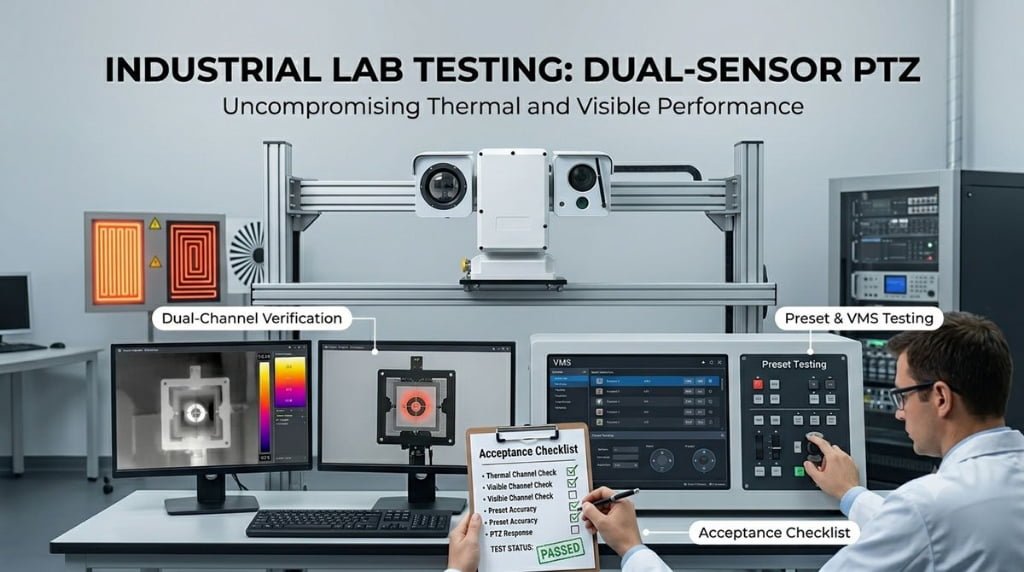
Use a Factory Acceptance Test That Resembles the Project
A useful factory acceptance test does more than confirm that two video channels appear on a monitor. It reproduces the intended lenses, payload, movement profile, cabling and software workflow.
Optical tests
- Compare thermal and visible fields of view at representative distances.
- Check target framing when switching from thermal to visible.
- Evaluate alignment at near, middle and farther project zones.
- Inspect visible stability at the intended verification zoom.
- Repeat the alignment check after multiple pan and tilt cycles.
- Test under day, twilight and night conditions where practical.
Motion tests
- Call presets from both pan directions.
- Check slow movement for stick-slip or visible vibration.
- Perform rapid repositioning followed by a stable dwell.
- Run the intended patrol sequence repeatedly.
- Observe cable behavior throughout the movement range.
- Check position recovery after a controlled power interruption.
Integration tests
- Connect the camera to the intended VMS version.
- Display and record both video channels.
- Call presets from the alarm workflow.
- Confirm operator override and user permissions.
- Review recorded thermal and visible video together.
- Interrupt and restore network communication.
- Confirm event logs, timestamps and alarm acknowledgement.
The NIST Video Surveillance Equipment Selection and Application Guide recommends defining user and functional requirements before equipment is selected. The same principle should govern acceptance testing: test the surveillance task, not only the hardware interface.
External reference: NIST Video Surveillance Equipment Selection and Application Guide.
A Practical JEC Product Reference
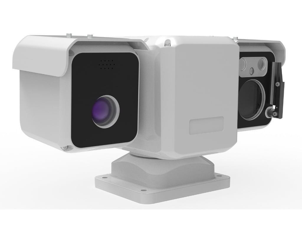
The JEC-PTZ-720 Series illustrates a compact dual-sensor configuration for projects that need visible and thermal imaging in a limited installation space.
According to the current JEC product page, the platform combines:
- A visible camera with a 4.8–158 mm lens and 33× optical zoom
- A 640 × 512 uncooled thermal detector with 12 μm pixels
- A 25 mm thermal lens with a listed 17.4° × 14.0° field of view
- Continuous 360° pan and ±90° tilt movement
- A 10–36 V power-input range
- An IP66 enclosure rating
JEC positions this model for mobile surveillance, perimeter patrol, industrial inspection robots, unmanned platforms and temporary deployment. Those applications favor compact integration and flexible movement.
This does not make one compact model the correct choice for every fixed industrial perimeter. A large site requiring narrow thermal fields of view, heavier optics or extended long-range observation may require a different JEC platform. Product selection should follow the site geometry, optical calculation and operating workflow described earlier in this guide.
Information to Include in the RFQ
Site and operating concept
- Facility type and protected assets
- Site drawing with camera positions and alarm sectors
- Target classes and required operator decisions
- Near, middle and far observation zones
- Continuous-coverage and PTZ-investigation requirements
- Existing sensors, VMS and communication infrastructure
Thermal and visible imaging
- Purpose of each imaging channel
- Required thermal field of view by sector
- Visible verification zoom requirement
- Expected thermal-to-visible handoff behavior
- Alignment requirements at representative distances
- Recording and operator-display requirements
PTZ and mechanical design
- Preset, patrol and tracking workflow
- Required movement speed and settling behavior
- Mounting height and support structure
- Wind, vibration and environmental exposure
- Cable routing and continuous-pan requirement
- Maintenance and calibration access
Software and project delivery
- VMS brand and software version
- Alarm source and handoff sequence
- Required streams, recording modes and user permissions
- Sample, pilot and production quantities
- OEM/ODM housing, firmware or branding requirements
- Factory and site acceptance procedures
JEC Resources for Project Evaluation
Buyers can review the JEC-PTZ-720 dual-sensor thermal PTZ camera and JEC’s broader thermal PTZ camera product range.
For projects requiring different payload sizes, optical configurations or observation distances, JEC also provides thermal imaging and EO/IR PTZ camera systems. The critical infrastructure security solution provides additional context for power, water, energy, transport and communication-facility applications.
JEC Dual-Sensor Thermal PTZ Video
The video can be used to show the product structure and PTZ movement. Project-specific imaging distance, VMS workflow and installation performance should be assessed using the proposed configuration and acceptance plan.
FAQ
What is the main advantage of a dual-sensor thermal PTZ camera?
Its main advantage is the ability to use thermal and visible imaging from one movable platform. Thermal imagery can help locate activity under difficult lighting, while visible imaging can provide additional scene detail for operator verification.
Can one dual-sensor PTZ provide continuous coverage of an entire perimeter?
Not necessarily. A PTZ observes one direction at a time. Sites requiring continuous coverage of several independent sectors may use fixed cameras, radar or fence sensors for persistent awareness and assign the PTZ to alarm investigation.
How should a thermal lens be matched with a visible zoom camera?
Compare field of view, scene width and target pixels at the actual working distances. Do not match the channels by focal length alone because the thermal and visible sensors may have different physical dimensions and resolutions.
Why can the target move when switching between thermal and visible video?
The two sensors occupy different positions inside the payload. Their optical axes may be aligned at a reference distance, but sensor spacing creates parallax at other distances. Mechanical tolerance and calibration also affect target position.
Which PTZ specification matters most for long-zoom verification?
No single value is sufficient. Minimum controllable speed, preset repeatability, backlash, settling time, holding stability and mounting rigidity all influence image usability at narrow visible fields of view.
Should the VMS record both thermal and visible channels?
That depends on the incident-review and storage requirements. The decision should be made before deployment so stream configuration, bandwidth, retention and alarm recording can be tested with the final VMS.
Is an IP66 camera automatically suitable for every outdoor industrial site?
No. The IP code addresses dust and liquid ingress. Corrosion, temperature, condensation, wind, vibration, solar heat, grounding and maintenance access require separate evaluation.
What should OEM/ODM buyers provide to JEC?
Provide the application, site or platform drawing, target classes, observation distances, thermal and visible workflow, housing limitations, power and interface requirements, VMS environment, quantity plan and required customization.
Request a Dual-Sensor PTZ Configuration Review
Send JEC your site drawing, alarm sectors, target classes, working distances, mounting conditions, thermal and visible imaging requirements, VMS platform and project quantity. The engineering discussion can then focus on field of view, optical handoff, motion behavior and acceptance criteria rather than a generic camera specification.
Contact JEC to discuss a project-based dual-sensor thermal PTZ configuration.